Extracting 3D Models From CesiumJS - Part 2: Terrain Map Parsing
en- CesiumJS Terrain Map Scraping
- CesiumJS Terrain Map Parsing
CesiumJS is a open source JavaScript framework for rendering 2D and 3D maps - everything from a local area to whole planets - in a web browser using WebGL. In the past few weeks I've been working on obtaining 3D model data in a situation where the only easily available way of accessing the data is through a CesiumJS based viewer. As far as I know, Cesium deals with two different kinds of 3D data: On one side, there's 3D models used for small-scale objects like buildings or trees, on the other side there's terrain maps.
The quantized-mesh File Format
In the previous article, I wrote about how to scrape
quantized-mesh-formatted terrain map tiles from a CesiumJS
web app. At the end of the previous article, we were left with a
bunch of .terrain files.
Luckily, the quantized-mesh format is documented fairly well in the specification:
The file starts with an 88-byte header consisting of:
- The center of the tile in earth-centered Cartesian coordinates.
- The height range covered by this tile, as distance from the earth's center. You'll see later why this is required.
- The parameters (center and radius) of the tile's bounding sphere.
- Coordinates of a «horizon occlusion point», used to simplify rendering: The point is chosen so that if it lies below the horizon, the entire tile is behind the horizon, and thus invisible, and does not need to be rendered. Cesium wrote an entire blogpost about this.
After the header follows the vertex data consisting of:
- The number of vertices.
- An array of horizontal coordinates, 0 means westmost, 32767 eastmost, everything in between is linearly interpolated.
- An array of vertical coordinates, 0 means southmost, 32767 northmost.
- An array of heights. Here the height range mentioned earlier comes in: 0 encodes the lower height bound, and 32767 encodes the upper bound.
The vertex data (the contents of the three arrays) follows a rather odd encoding with two specialties:
- Each vertex' data is not encoded as absolute values, but as deltas to the data of the preceding vertex. Only the first vertex' data is encoded with absolute values.
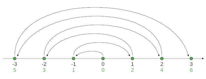
- The individual numbers (unsigned 16-bit integers) are not encoded as two's complement, as is common in today's computing, but as something Cesium calls "zig-zag encoding": The sequence of encoded numbers alternatingly encode positive and negative numbers, as depicted in Figure 1.
Luckily, the quantized-mesh specification provides pseudocode for decoding this data.

The specification states that this encoding is chosen «in order to make small integers, regardless of their sign, use a small number of bits».
I'm not entirely sure why they want to achieve this (after all, each number takes up the same amount of space, no matter how many bits are zero), but I suspect this is done to potentially further reduce the resulting size if the file is compressed, esp. when using HTTP's gzip transport compression.
Following the vertex data is the index data: Similar to a lot other file formats dealing with 3D data, a quantized-mesh file ultimately encodes a set of polygons, or to be more precise, triangles. The index data describes a series of triangles trough:
- The number of triangles.
- An array of vertex indices, with three indices per triangle, one for each corner of a triangle.
A vertex index is simply the index of a vertex in the aforementioned vertex data. This indirection is used because most vertices are part of multiple triangles, so some space can be saved. In addition, the index data is again encoded somewhat specially (but a different kind of special than the vertex data). I did not look too deep into understanding what exactly is done and why it is done, but again I assume this is to make the file more compressible.
Depending on how many vertices the file contains, the indices are encoded as either 16-bit or 32-bit integers, and padding is inserted before the index data to ensure memory alignment.
Finally, the file contains four more vertex index lists, describing which vertices are part of each of the four edges (western, southern, eastern, northern) of the terrain tile.
Optionally, there can be some extension data added to the end of the file, such as normal vectors for lighting computation when rendering the terrain, but this is beyond the scope of this post.
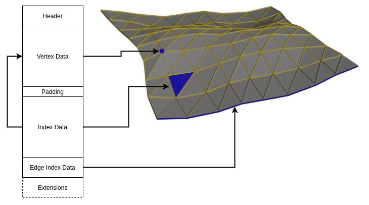
To sum it up, Figure 2 shows an illustration of the file format and which parts encode which features of a 3D terrain.

Parsing The quantized-mesh Files
I wrote a simple converter script that parses a quantized-mesh file and creates an ASCII STL file containing the terrain. The STL coordinates are in meters, using Cartesian coordinates with the origin in the Earth's center. To be more precise, the coordinates are in EPSG:4978.
You can find the script on Gitlab.
The next article in this series will cover the scraping of 3D building models.